Johannes Firzlaff, Department of Wood Technology,
Fachhochschule Eberswalde
Foundations for Numerical Computation of
Notch Depths of Round Timber Shoulders
Preliminary Remark
This thesis is a revision of a lecture given on the occasion of an
examination in the subject of Technical English. Although it is based on
my German edition published "above" this page it is no
translation.
To start with we should consider the
Shoulder and its Geometry
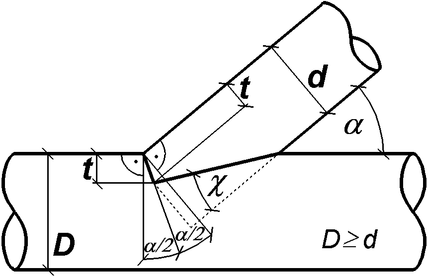
A shoulder is one possible carpenter´s joint of two wooden rods. It
can only be used for compressive force transmission. The axis of the rod
to be fixed is inclined to the axis of the incorporating rod.
The rod force Falpha is divided up into two parts -
shoulder force Falpha/2 and bevel force Fchi
- and transmitted by contact in two planes - shoulder plane Aalpha/2
and bevel plane Achi.
The amount of the shoulder angle alpha/2 is given by the
joint angle alpha. The bevel angle chi depends on the
notch depth t: An increasing notch t decreases bevel angle
chi.
Engineers should endeavour to keep notch depths as small as possible in
order to reduce the weakening of the cross-section-area of incorporating
rods. This is the motive for this thesis.
It is postulated: Contact surfaces without friction, exact fits and
rigid bodies. The diameters of the incorporating rods must be at least as
big as those of the rods which are to be fixed. Given that, the
derivations can also be applied to incorporating squared timber instead of
incorporating round timber.
Being an anisotropic material the strength of wood depends on the angle
of grain to stress. Here the German standard DIN 1052 [1988] is used for
determining the so called safe working stress.
Anything will be said about the allowed notch depth t and joint
angle alpha, the length of safety-wood in front of the joint and
the problem of the arrangement protection.
Study of Nexus, Strategy of Solution
The rod force Falpha and the joint angle alpha
are given. So the shoulder angle alpha/2 is also defined by the
geometric definition of the shoulder. With this shoulder plane safe
working stress sigmaalpha/2 swsand direction of
shoulder force Falpha/2 are determined. Shoulder force
Falpha/2 and shoulder plane Aalpha/2
must be perpendicular to each other because no friction is postulated.
Shoulder plane Aalpha/2 takes the form of a segment
of an ellipse and is a function of notch depth t and joint angle
alpha. The necessary area of the shoulder plane
sigma = F / A <=> Aalpha/2
= Falpha/2 / sigmaalpha/2 sws
is calculated from the values of shoulder force Falpha/2
and shoulder plane compressive safe working stress sigmaalpha/2
sws.
Quantity and orientation of the bevel plane Achi,
also shaped like an ellipse segment, and therefore the direction of the
bevel force Fchi are functions of notch depth t
as well. As above shoulder force Falpha/2 also bevel
force Fchi must be perpendicular to its pertinent
plane.
But the direction of bevel force Fchi has also an
influence on the quantity of shoulder force Falpha/2!
This is illustrated by the triangle of forces.
So each change of notch depth t does not only result in changes
of bevel area Achi and particularly shoulder area Aalpha/2,
but also exercises an influence on the values of both components shoulder
and bevel force Falpha/2 and Fchi
in which rod force Falpha is to be dissected.
Consequently shoulder stress sigmaalpha/2 varies
directly by corrections of notch depth t and indirectly as a
feedback by change of value of shoulder force Falpha/2
which ensue from notch depth t correction simultaneously.
Now then notch depth t has to be chosen to such a degree that
this inequation
Aalpha/2 >= Falpha/2
/ sigmaalpha/2 sws
is served.
At the same time the bevel tension sigma chi value
must not overstep both safe working stresses sigma (90°-chi)
sws and sigma(90°-alpha+chi) sws in the
bevel plane Achi which come up to different quantities
on the side of the rod to be fixed and the incorporating rod. The
difference of the quantities results from the different angles.
rod angle alpha
rod force Falpha(look next figure)
shoulder angle alpha/2
shoulder force Falpha/2(look next figure)
bevel angle chi
bevel force Fchi(look next figure)
notch depth t
diameter of the rod to be fixed d
angle of grain to stress in shoulder plane alpha/2
angle of grain to stress in bevel plane of rod to be fixed 90°-chi
angle of grain to stress in bevel plane of incorporating rod 90°-alpha+chi
chi = arctan [ (d-t) / ( t*tan(alpha/2) + d/tan(alpha)
) ]
Remark: shoulder and bevel plane form a right angle if chi
= alpha/2. |
 |
Having done this preliminary work the route of solution is marked by the
inequation above: Formula-derivations for the two components of rod force,
safe working stresses and ellipse-segment areas.
The first point in the order just fixed is the
Rod Force and its Components
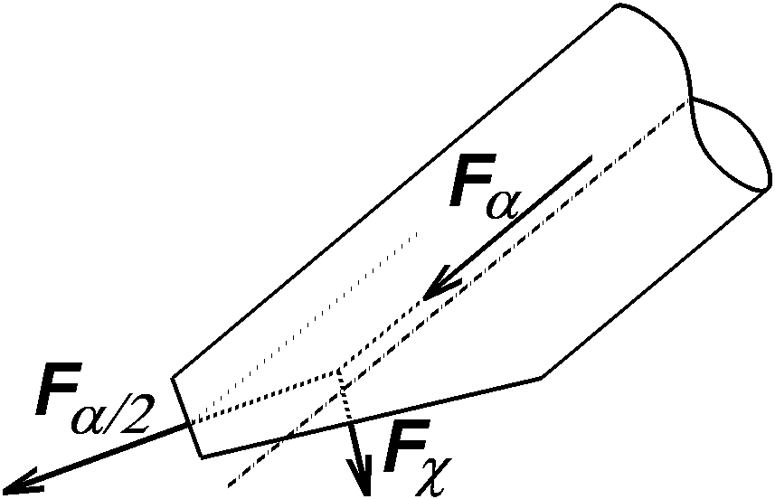 |
Remark: Positive forces pull at the contact surfaces.
The dissection of rod force Falpha into
shoulder force Falpha/2 and bevel force Fchi
results in the following triangle of forces after bevel force Fchi
has been translated. |
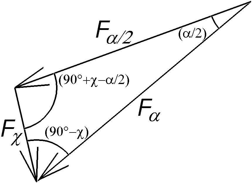 |
The values of the components follow from the sine theorem:
Falpha / sin(90°+chi-alpha/2)
= Falpha/2 / sin(90°-chi)
= Fchi / sin(alpha/2)
<=>
Falpha/2= Falpha*cos(chi)/
cos(chi-alpha/2) and
Fchi = Falpha*sin(alpha/2)
/ cos(chi-alpha/2) |
The next step is the
Calculation of Safe Working Stress at any Angle phi
As mentioned earlier here the formula according to German standard DIN
1052 [04.1988] is used. The compressive safe working stress by angle grain
to wood phi sigma phi sws is calculated from
the compression strength parallel >(par)<to grain minus the
difference strength perpendicular >(per)< to strength
parallel to grain multiplied by sine of angle phi.
sigma phi sws = sigmapar
sws - (sigmapar sws - sigmaper sws)
* sin(phi) ;
sigmaphi; sigmapar; sigmaper
<= 0 (free from DIN 1052 T 1 [1988]
The last single point is the
Surface Calculation of Ellipse Segments (Shoulder and Bevel Plane)
An ellipse can be described as a projection of a circle on a inclined
plane. In this case the circle corresponds to the cross-section and the
ellipse to that shoulder plane of round timber which will follow from a
notch depth t in size of diameter d.
While the length of the minor axis of the ellipse coincides with the
round timber diameter the major axis assumes a value increased by the
factor 1/cos(alpha/2).
Smaller notch depths (t < d) result in shoulder
planes shaped like ellipse segments. These are projections of circle
segments, prolate in one direction and perpendicular to the chord with the
same factor 1/cos(alpha/2).
The circle segment area is calculated from two terms of a sum: The area
of the circle sector reduced by two triangles which make the
difference to a circle segment.
Circle-Segment:
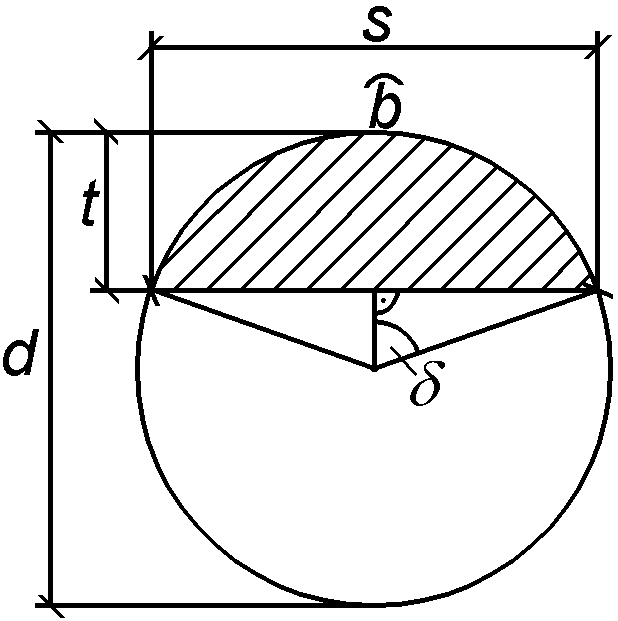 |
s = 2*[ (d/2)^2 - ((d/2) - t)^2
]^0,5 = 2*[d*t - t^2]^0,5
delta = (barc/2) / (d/2) <=>
barc = d*delta = d*arccos[
((d/2) - t) / (d/2) ] = d*arccos[ (d
- 2*t)/d ]
Acircle-segment"alpha/2" = ( d^2*pi*barc
/ (4*d*pi) ) - (d*t - t^2
)^0,5*((d/2) - t)
= (1/4) * [ d^2*arccos( (d - 2*t)/d
) - 2*(d*t - t^2)^0,5*(d - 2*t)
]
Ellipse-Segment: Aalpha/2 =
[1/cos(alpha/2)]*Acircle-segment"alpha/2"
|
In bevel surface calculation Achi alpha/2 is
replaced by 90°-chi and t by d-t. The prolate
factor changes to 1/sin(chi).
Now the individual results can be pooled in our point
Compilation of the Individual Studies
Notch depth t has to fulfill the following systems of
inequations:
Aalpha/2 >= Falpha/2
/ sigmaalpha/2 sws and
Achi >= Fchi / sigma(90°-chi)
sws and Achi >= Fchi
/ sigma(90°-alpha+chi) sws ;
in which
Aalpha/2 = (1 / (4*cos(alpha/2)) )*[ d^2*arccos(
(d - 2*t)/d ) - 2*(d*t - t^2)^0,5*(d
- 2*t) ]
Achi = (1 / (4*sin(chi)) * [ d^2*arccos(
(2*t - d)/d ) - 2*(d*t - t^2)^0,5*(2*t
- d)]
Falpha/2 = Falpha*cos(chi)
/ cos(chi-alpha/2)
Fchi = Falpha*sin(alpha/2)
/ cos(chi-alpha/2)
sigma alpha/2 sws = sigmapar sws
- (sigmapar sws - sigmaper sws)*sin(alpha/2)
sigma (90°-chi) sws = sigmapar sws
- (sigmapar sws - sigmaper sws)*cos(chi)
sigma (90°-alpha+chi) sws = sigmapar
sws - (sigmapar sws - sigmaper sws)*cos(chi-alpha)
chi = arctan[ (d-t) / (t*tan(alpha/2)
+ d/tan(alpha)) ]
This system with its integral equations can be used to check notch depth
t already given but not for expansion of a simple explicit notch
depth formula. A second possibility of use is numerical calculation based
on the computer. This facility shall be returned to after the résumé.
Résumé
In brief the shoulder and its geometric details as a carpenter´s
joint of wooden rods were looked at.
Then the nexus was studied where theoretic and complex assumptions were
made.
In anticipated consequence of the complicated function for calculating
the contact areas the rod force was exactly dissected in its components
since indeed the computer was intended for calculation anyway.
For safe working stress calculation the German standard DIN was applied.
General formulae for each angle grain to stress could be retrieved by
geometric analysis of the sketch.
Finally the function for contact areas was worked out of a prolate
circle fragment.
The findings of the research is a system of inequations which can be
used for numerical computation.
View of Eccentricity of Rod Force
First please have a look at the second sketch. The vectors
Falpha/2 and Fchi act on the
centres of gravity of their respective planes in normal directions. These
points are calculated in their distances to midline in cross-section by
the formula
a = s3 / (12 * A).
For s and A the expressions from the
circle-segment-calculation are to be applied. Then they are projected in
rod direction into their respective planes. Finally the eccentricity of
the rod force is constructed by graphic addition of the two vectors.
The analytic determination of the resultant-position with
the model introduced here seems to become very complicated. Moreover it
must be noticed to be on the unreliable side by doing so because of the
idealized hypothesises.
This is illustrated in the above mentioned sketch: The thinnest
dotted line shows the result of eccentricity determination according to
the ordinary principle:
Dissection of rod force only in shoulder plane in
normal force Falpha/2 N = Falpha
* cos(alpha/2) and
transverse force Falpha/2 T = Falpha
* sin(alpha/2).
However I would like to point out that my method is
qualified just for round timber, too: Notches with depths as deep
as their rod-to-be-fixed-diameters produce bevel plane areas of nought!
Thanks
I express my thanks to Mr Strey, Fachhochschule Neubrandenburg, for
checking (the mathematical part of) this thesis.
Furthermore I thank Mr Dietterle and Mr Bonadt, our specialists in
information technology, for their patient help in the multitude of
problems I got in preparation of this presentation.
Application
The work presented here is applied to a MICROSOFT EXCEL©
7 file. With this application notch depths t, diameters d
and rod forces Falpha can be tested for accomplishment
of the inequation system without any nomogram and furthermore
automatically optimized by mouseclick. It is published on the internet "besides"
these "foundations".
Click here to have opportunity to get an
impression of this program. It is only available in German language.
All Rights Reserved
I reserve all rights to this thesis and to the computer program. For
propagation (and further propagation) in printed media my permission is
needed.
For use of my program it is necessary to read and understand the German
version of this thesis and the German instructions for use.
Eberswalde, Campus Möller-Straße, 10.09.1997
(10th September 1997)
(Grammatical and stylistic revision on 13th November 1997)
Johannes Firzlaff |
 |
Survey of my themes
Homepage of my
Fachhochschule Eberswalde